Drawing 3D with watchX

Hey everyone,

I wondered whether I can make a script that shows points and lines in the 3D space or not. Since I am a mechanical engineer, I am not that good with coding, but I am really good with analytic geometry and trigonometry. So, I have decided to do it.

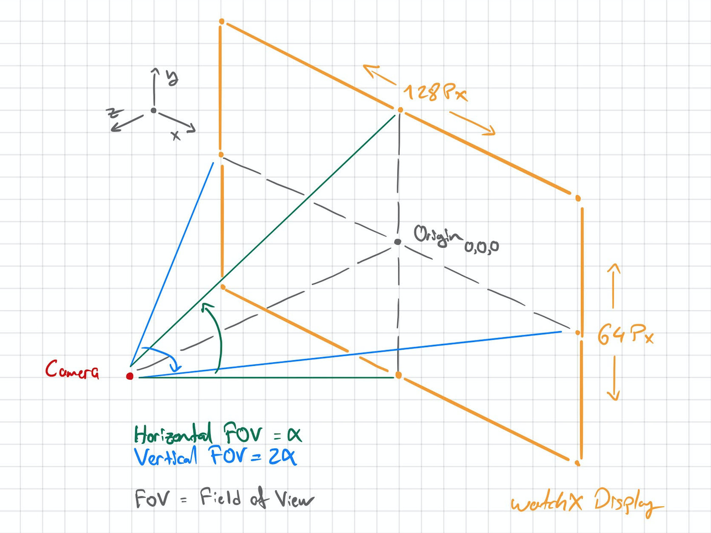
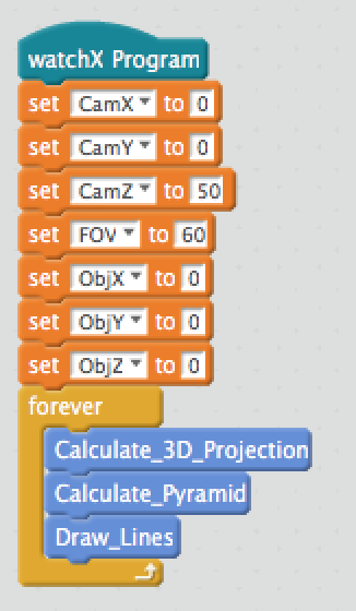
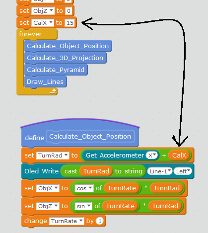
First I need to define my camera setup and 3D space. We are looking at 3D images in our computers in a 2D projected perspective. What I mean is that the 3D parameters are projected to our display with respect to our camera properties such as distance from the object, orientation, field of view etc… That’s why defining the camera is important.

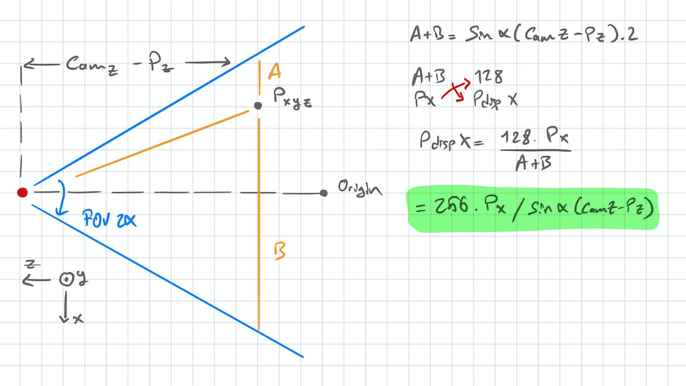
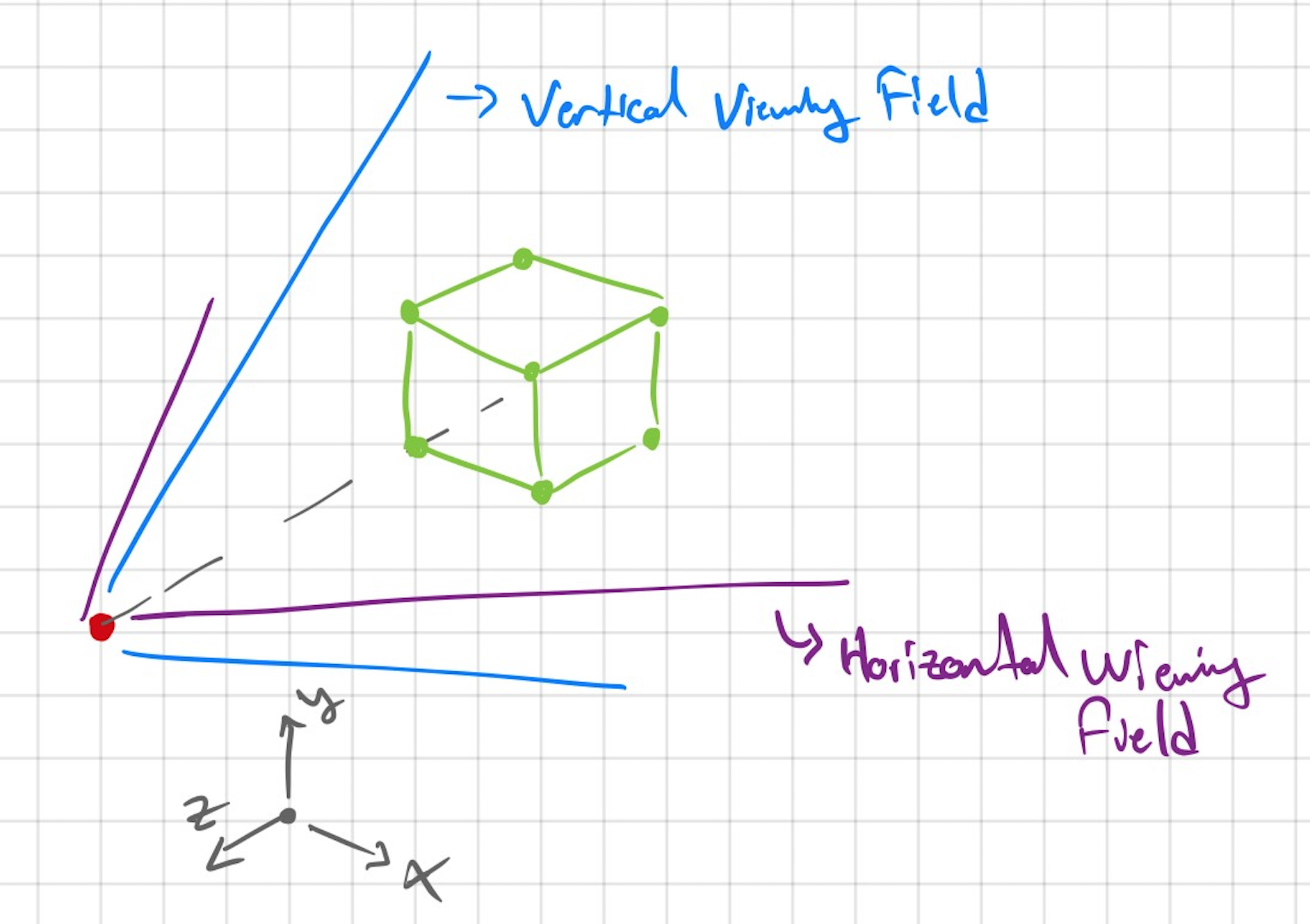
And my approach is something like a two planar sphere model. I may sound dumb but I promise it will make sense… We have a 2D coordinate system in our displays. Each pixel is defined with X and Y coordinates. Therefore I need to evaluate where does a point in 3D space projects at the screen. This means I need to do two sets of calculations for each horizontal and vertical data of the projection.

Here you can see my idea of two planes intersecting and showing the field of view of the camera.

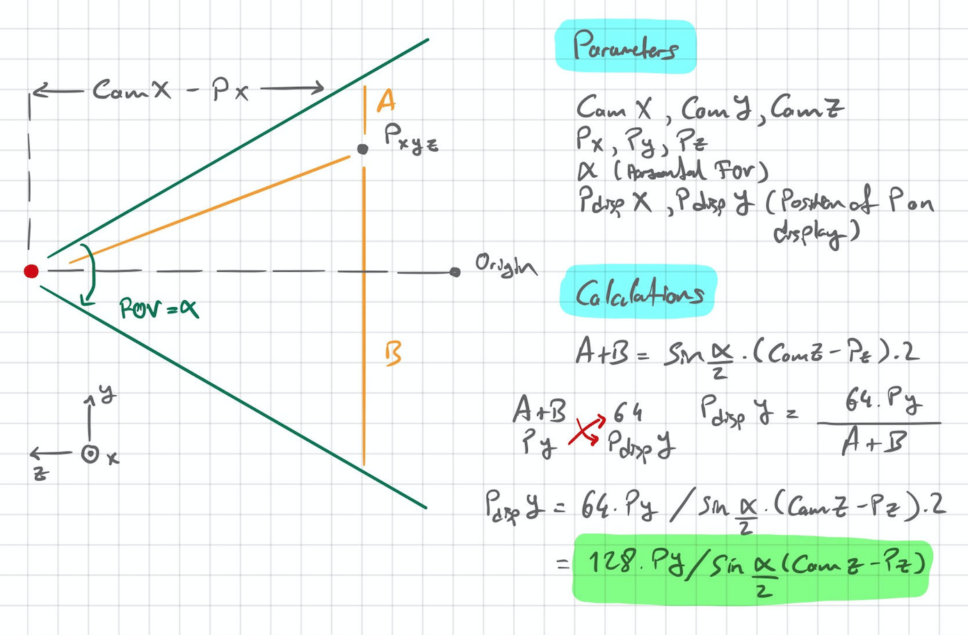
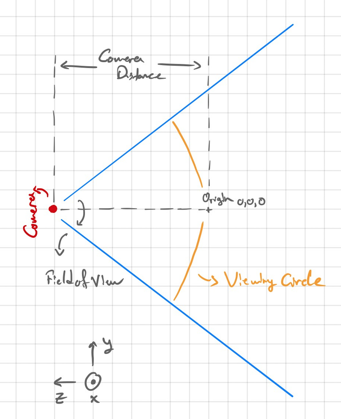
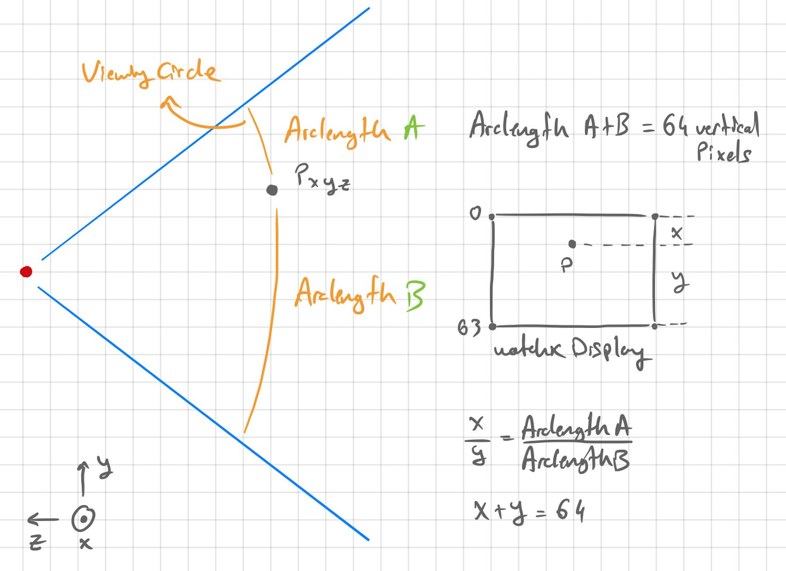
From this point on, I will only focus on the explanation in vertical space. The horizontal space will be the same. Here you can see a phenomenon that I named as the viewing circle. This circle represents the vertical 64 pixels of watchX display. The origin point stays right in the middle of the arc. Therefore the vertical position of the origin will be right in the middle too.

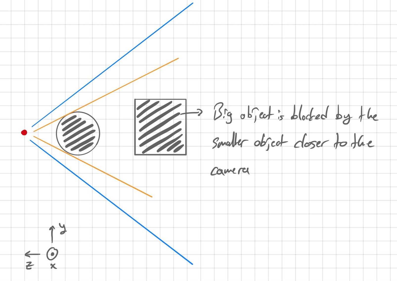
Here you can see that a smaller object closer to the camera can block the bigger object which is further away.

If I want to represent a point Pxyz, I have to calculate the relation between Archlength A and B. This relation will result in the vertical position of the point Pxyz at watchX display.

In the next post, I will try to calculate the viewing circle radius (distance between camera and point) Archlength A and B. Than I will try to do the same for the horizontal space. After successfully doing these I will try to represent point clouds in 3D environment and I will try to make wireframe models in 3D.

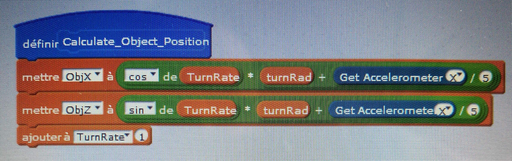
My final goal is to manipulate the camera with the help of IMU and have a look at the objects in different angles. :slight_smile:

3 Likes

Hello, thank you for this guide. I started to wonder about those stuffs with the 3d gyro cube example but stopped my reflexion. I’ll be able to go it back thank to this

1 Like

I’ve put together a Scratch code that you might saw at our Instagram stories. I will make it more clean and understandable and put it here today :slight_smile:

1 Like

I have tried to derive the projection formulas for my theory in my first message. It required to make complex calculations for arclength formulas. Therefore I decided to change my approach a bit and come up with a line based model. The calculations in this form is much more simple than the previous approach.

You can see that I made a wrong assumption in the first post. The “Field of View” data for vertical and horizontal calculations are different because the aspect ratio of the display is 2:1

You can see that the projection formulas for X and Y on display for a point defined in the space are marked as green.

In the next post, I will put a code together to visualize a pyramid and manipulate it’s position to see the perspective effects.

And here is our first 3D image!
A pyramid made of 4 points, 4 polygons and 6 lines.

Let’s have a look at the code. Here is our main code frame:

We have defined the camera position, field of view, object position at first. Then, we are running the 3D projection formulas, Pyramid calculation and drawing line functions. I have decided to separate the main code into subfunctions so that the code will look tidy.

We have 4 different points to define the pyramid, xyz for every point means that we have to define 12 different parameters for 4 points. And if we want to manipulate the object, we have to redefine the points again. I decided to put all of these points into a function and derive them from the origin point of the object. You can see that I have defined ObjXYZ already. Here is the function for point calculation:

Here we are calculating the X and Y coordinates of every point projected on the watchX display. These formulas are derived in the previous post with respect to my 3D Projection theory.

This function draws lines between the points to construct a wireframe representation of the pyramid: (I did not use the draw pixels function but it can be used as well.)

Next, I will move the object in space so that we can see the perspective and realize the object in 3D.

And you can download the current scratch code from here.

Sorry for the message flood :slight_smile:

But I wanted to go on a little bit. As I said, I wanted to move the Pyramid in front of the camera in the path of a circle. First we need to define the maths behind;

Than the code;
17

And the result;

1 Like

This is fantastic Enes. I glad to see such a powerful project has programed by scratch.

I am wondering if it is possible to code an object is moving freely in the 3d space (without predefined path) and continue its motion in space by bouncing from edges.

1 Like

Just perfect. This is probably the most powerfull output of the watchx and one of the best guide I’ve ever seen. No video but written and clear explanations.
I’m hurry to try it, see how to link movment to gyro and try more complex drawings if there is enough place on the ram.
I’ll post my video

1 Like

https://youtu.be/F51ppuT3l0s
As promised

To add accelerometer :

2 Likes

Looks good. And the object looks cool too. :relaxed:

Wow this is so powerful:) I can see game development through Scratch :heart_eyes:

Makes fun (with a bit calibration)…

grafik

1 Like